1994issue C091-3
Centering a dual lowpass bandpass on a counted cycle
Treat the two cutoff periods as geometry before any overlay is read. Two three-pole lowpass recurrences carve a bandpass series, their geometric mean is the intended rhythm, and a dominant cycle counted from successive turning points checks that the band is aimed at the series on the chart.
- A bandpass series is the difference of two three-pole lowpass recurrences that share the same closing-price input and differ only by cutoff period.
- The pass-band center is the geometric mean of the two cutoff periods, and it also scales the one-bar leading companion.
- When crossings of the bandpass series and the leading companion arrive after price turns, the construction response is to recount peaks and troughs and recenter the band.
- An alternative cutoff pair of 10 and 20 is given so a counted 14-bar cycle sits at the center of the pass band.
Read the cutoffs before the overlay
This archive article restates a historical filter construction. Two three-pole lowpass recurrences share the same closing-price input and use different cutoff periods. Their difference is the bandpass series: the variation that remains between those periods.
Editorial: cutoff choice is geometry first. The two cutoff periods carve the pass band, the pass-band center is their geometric mean, and a dominant cycle counted from successive turning points is the check that the band is aimed at the series actually on the chart.
Two lowpass recurrences carve the band
Each lowpass-filter is a three-pole recurrence whose coefficients depend only on its cutoff period. The coefficient triple is computed from that period with an exponential of minus pi over the period, a cosine term that uses the factor 1.732, and an exponential of minus two-pi over the period.
Each recurrence is initialized by copying the first three closing prices into the filter column. After that seed, the recursive update begins. The lowpass-filter is then driven by prior outputs plus a four-bar weighted close.
Bandpass and leading series from the two Butterworth cutoffs
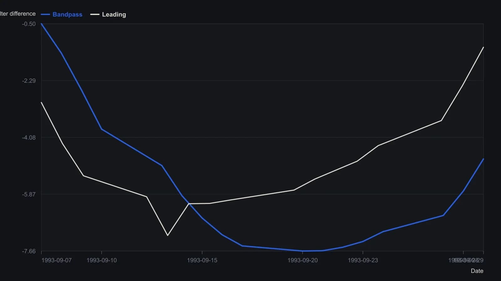
Filter 1 cutoff is 10 bars, filter 2 is 35 bars; the sidebar states the pass-band center as their geometric mean, P center = 18.71. Bandpass and leading columns are blank until 930907 and 930908.
The pass-band center sets the intended rhythm
The pass-band center is the square root of the product of the two cutoff periods. That geometric mean is the intended cycle length inside the band.
A leading companion is formed from the current bandpass value plus its one-bar change scaled by that center period over two-pi, then divided by 1.414.
Recount turning points when crossings lag
On the worked Treasury-bond futures plot, the marked events are crossings of the bandpass series and the leading companion.
When the observed cycle shortens relative to the chosen cutoffs, those crossings occur after price turns. The construction response is to recount peaks and troughs and recenter the pass band. The dominant cycle is the cycle length inferred by that count, then used to place the pass-band center between the two cutoffs.
The worked pair of cutoffs is 10 and 35. An alternative pair of 10 and 20 is given so a counted 14-bar cycle sits at the center of the pass band.
All readings on this track · 9 readings
- 1991Constructing a coincident moving average as a lowpass filter
- 1994Centering a dual lowpass bandpass on a counted cycle
- 1997Zero-lag cycle filters can fail on a price series
- 2002Constructing zero-lag finite-impulse-response and exponential smoothers
- 2010Constructing cycle versus trend mode filters
- 2010Constructing a trend filter as a low-frequency model
- 2015Whitened lowpass filters for trend and countertrend
- 2016Building Nyquist-safe lowpass trend filters
- 2018Constructing a Finite Impulse Response Filter compared with Exponential smoothing